Author

Introduction
As experts who have spent years researching the security of hardware platforms developed by Intel, we acknowledge that Intel’s Converged Security and Management Engine security architecture is highly reliable and was designed by top-notch professionals.
From an architectural perspective, if all its individual components function as intended, it is challenging to find a vulnerability, that, even hypothetically, could lead to irreparable consequences, calling into question the correctness of the decisions made.
Undoubtedly, Intel’s confidence in the reliability of its lowest-level protection, also known as the Root of Trust (RoT), can be attributed to the highest level of privileges granted to the Intel CSME subsystem, including unrestricted access to memory and hardware containing user data. This RoT is based on cryptography, specifically the skilled application of asymmetric and symmetric encryption algorithms, to ensure the confidentiality and integrity of the executable code and data of Intel CSME and other platform subsystems.
Our goal is not to reiterate the security of Intel CSME, as Intel has already done so in a dedicated document that thoroughly examines their security architecture, starting from the lowest level (root encryption keys) and covering topics such as module integrity control, remote attestation, and the Trusted Platform Module (TPM, [1]).
In this study, we intend to delve into specific details and demonstrate how incorrect implementation and inconsistent use of otherwise correct and secure mechanisms, in the context of the overall security model, can lead to severe consequences, allowing access to root encryption keys and rendering the security model ineffective.
It is essential to note that, since the primary objective of the proposed security model is to guarantee the infeasibility of accessing root encryption keys, an incorrect implementation of this model renders its current application meaningless, at least until the flaws discussed in this study are addressed, which, as will be shown below, is only possible in new platforms, as the incorrect implementation is hardcoded in non-reprogrammable memory and serves as the architectural foundation for some fundamental mechanisms embedded in the Intel CSME firmware.
In our study, we will frequently refer to the document describing Intel CSME security [2], using its terminology, concepts, and diagrams.
Intel CSME’s Root of Trust
The Intel CSME security architecture is based on two fundamental elements that form an unbreakable foundation, which should not be compromised under any circumstances. If this foundation is damaged, the entire “building” will collapse, and there are no mechanisms to prevent this from happening. These two root elements have different purposes but complement each other, and only their complete compromise makes it possible to bypass all the defense mechanisms embedded in the Intel CSME security model.
These are the two elements on which the Intel CSME Root of Trust is based:
- Security Fuses, which are unique to each crystal instance, whether it’s a chipset or a System-on-Chip (SoC). They are generated by a special entity called the Key Generation Facility (KGF), which ensures their uniqueness, confidentiality, and integrity until they are programmed into the crystal’s One-Time-Programmed (OTP) configuration. The KGF is likely to be a secure server connected to the factory programmer via a secure channel, operating at the final stages of the High-Volume Manufacturing (HVM) process.
- The Fuse Encryption Key (FEK), which encrypts the Security Fuses using the symmetric encryption algorithm AES before they are written to the OTP configuration. This key is not unique and is shared among all instances of a particular microarchitecture. For example, all chipsets of the Tiger Point generation or all SoCs of the Goldmont microarchitecture share the same FEK.
Figure 1 illustrates the Security Fuses and the Fuse Encryption Key, as well as their place in the overall hierarchy of encryption keys that implement various mechanisms and ensure the security of Intel CSME. This figure is based on an Intel document [2], page 15, Figure 4, “Keys Derivation Conceptual Key”.

In the figure above, the Security Fuses are represented by a red rectangle on the right with labeled “Chipset Key Fuses (256 bit)”. However, the Chipset Key Fuses are only part of the Security Fuses, which also include fuses for the EPID Private Key, EPID Group ID, PTT Endorsement Key Counter, and Debug Enabled Chipset Key (see [2], Section 4.1.1.1, “The Fuse-Encryption Hardware Key, the Chipset Key and its Derivatives”).
It’s not hard to guess that these root encryption keys form the foundation of trust for the technologies implemented in Intel CSME, which Intel confidently presents in various presentations, without any doubt about the possibility of their compromise. In fact, the phrase “hardware root of trust” is intended to inspire confidence in the average user, who is not familiar with the details of the implementation and operation of hardware components, and to make the public believe that the reliability of hardware is always higher than that of software systems. But is this really the case?
Let’s look at the main points that make up the protection of the Security Fuses.
Figure 1 only shows that the Chipset Key Fuses are inputs for an AES decryption procedure with a 128-bit encryption key (blue circle with the number 4), but it omits all the details related to the storage and extraction of the binary data that make up the Security Fuses. It is precisely the implementation of these specific details that makes or breaks the security of both the Security Fuses and the entire platform.
The security of the Security Fuses is based on:
1. The use of One-Time-Programmed memory, based on E-FUSE technology, to program the Security Fuses into the crystal. At the photolithography stage, the E-FUSE schematics are presented in an initial (unprogrammed) state, allowing the writing of any binary data – both zeros and ones. At one of the final stages, which takes place during the fabrication of the processor or system logic chip on the factory conveyor, the OTP configuration is written using industrial programmers that are electrically connected to the contacts of the finished chip. This allows a unique configuration to be set for each crystal instance, which is exactly what is required to assign the generated Security Fuses to each chip.
Once the E-FUSE data is written, it cannot be rewritten because the programming process causes the internal conductors on the crystal to burn out due to the passage of high current generated by the E-FUSE controller. This controller, called the Fuse Controller, is responsible for both programming the Security Fuses and securely reading and transmitting them to the required hardware module, which is authorized to request them.
2. The encryption of the Security Fuses immediately after they are generated in the Key Generation Facility.
This level of protection keeps the data secure: first, during the transmission from the KGF to the HVM conveyor at the factory, and, second, in the event that the Security Fuses are extracted from a working chip instance using reverse engineering techniques. Attackers will not be able to use the root keys that make up the Security Fuses to decrypt the working data of the Intel CSME firmware (which was once executed on the chip that underwent such analysis), since this requires knowledge of the encryption key of the Security Fuses themselves.
This key, called the Fuse Encryption Key or simply the Hardware Key in Figure 1 (red rectangle on the left, marked with an arrow), is itself an important element of the Intel CSME security model, as mentioned above, and Intel uses special methods to protect it, which will be described separately below.
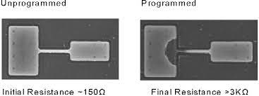
The previously mentioned reverse engineering techniques are based on the use of scanning electron microscopes (SEM) and layer-by-layer analysis of the CMOS elements that make up the logic of the silicon crystals, which can detect the programmed E-FUSE data because their burnt-out conductors change their structure in a way that is visible under an electron microscope (see Figure 2).
Although such analysis is more complex than reverse engineering of hardware logic or reading ROM data of integrated circuits, it is quite possible with the appropriate skills and high-resolution equipment.
It should be noted that such analysis is destructive in its nature and renders the microchip inoperable, but the extracted encryption keys (if they are stored in E-FUSE in plaintext) can be used to gain access to information created using this chip, as well as to impersonate it — that is, to emulate this chip in internet services based on remote authentication, in order to gain access to protected data intended exclusively for controlled use on genuine Intel equipment, in technologies such as DRM. These technologies do not deliver the protected data to users, but rather transmit it directly to hardware playback devices, allowing users to view the data, but not copy it.
3. A centralized mechanism, implemented in the Fuse Controller hardware logic, which processes read requests and transmits the Security Fuses to internal devices within the Intel CSME subsystem.
This platform device is located outside the Intel CSME domain, as it not only provides and protects the Security Fuses but also performs the function of storing configuration information for devices (hardware OTP configuration). Not only devices within the Intel CSME subsystem but also main platform devices, such as CPU cores, memory controllers, USB controllers, and others, have their own OTP configuration, which is programmed at the final stage of Intel chip production.
Furthermore, some devices, such as CPU cores and the power management microcontroller (PCU or P-UNIT), also use encryption and store their root keys in OTP memory, for example, to implement the Intel Software Guard Extensions (Intel SGX) technology.
Therefore, the Fuse Controller IP block is a common device that is accessible to all platform devices with specific configuration requirements.
This configuration information is transmitted over a special service bus called the IOSF Side Band.
IOSF, which stands for Intel On-chip System Fabric, is a proprietary specification for several data buses and protocols that devices use to interact with each other within Intel platforms. This set of IOSF buses (including IOSF Primary, IOSF Side Band, and IOSF DFX) has replaced the PCI Express bus for implementing internal interaction between IP blocks within a single crystal. Initially developed for ultra-mobile platforms (based on the Intel Atom SoC), the IOSF specification quickly became the primary communication mechanism for both system logic chipsets and processor crystals in desktop and server systems.
As a result, all Intel platforms released to date are based on IOSF, and the PCI Express bus is now used only to connect external devices to the platform.
Within the IOSF bus, each device is assigned a unique identifier, the SAI (Security Attribute of Initiator), which remains the same for the same device even across different platform types. For example, the ATT bridge from the Intel CSME domain to the main platform devices always has an SAI of 0x20 (in DFX Green/Locked mode) on both Atom and desktop/server platforms.
In addition to the SAI, each device connected to the IOSF Side Band has a unique Port ID, which is used for packet routing purposes.
However, the Port ID of devices on the IOSF SB does not match for different platforms and processor/chipset models. Thus, the SAI identifies the device for security and access control purposes, while the Port ID is used for addressing on the bus.
It should be noted that there are special bridges on the IOSF SB, for example, between the processor and the chipset, which convert the Port ID according to predefined tables, but the SAI of device requests remains unchanged during such conversion.
For instance, when accessing the P-UNIT on the Intel Rocket Lake platform, the Intel CSME firmware uses its Port ID of 0x90, but the SB_BRIDGE between the PCH and CPU converts this identifier to 0xe2, which is used locally within the CPU domain (North Complex), while the SAI of 0x20 remains unchanged. This allows devices to implement access control based on universal access masks (for read, write, and configuration rights) without worrying about the Port ID of a particular client device on a given platform.

The Fuse Controller device contains a special table called the Fuse Distribution Look-up Table (FDLT), which specifies the address and length of the data to be transmitted from the common E-FUSE array for a specific Security Attribute of Initiator (SAI) and Port ID when requesting Security Fuses or hardware configuration.
If a request is made with an SAI that, according to this table, should not come from the specified Port ID, or if it is not mentioned in the table at all, then the request is rejected (completed with a special error status). At the same time, the hardware configuration and Security Fuses are requested using special operation codes of the IOSF Side Band bus (0xb8 and 0xba for hardware configuration, 0xbb for Security Fuses). Additionally, the Fuse Controller analyzes the current value of the DFX Secure Policy, which indicates different platform debugging levels, such as Red and Orange Unlock (see [4], page 6), and transmits the Security Fuses only if the platform is operating in Green/Locked mode.
More specifically, the DFX Secure Policy value is also a key attribute of the FDLT table data, and in Unlocked modes, instead of the production Security Fuses, a special debug-enabled key is issued, which, although unique to the platform, does not allow it to be verified in Intel EPID remote attestation technologies and does not provide access to the firmware data operating in Locked mode.
This is how the protection of CSME Security Fuses is implemented by the Fuse Controller: they can only be obtained on request from the Intel CSME hardware domain (through the appropriate SAI) and only in DFX Secure Policy Green.
4. Limiting the scope of the executable code of the Intel CSME firmware that has access to the original Security Fuses.
When examining the part of the Intel CSME firmware that is stored in non-reprogrammable memory (ROM) and starts executing immediately after the CSME subsystem is started, it becomes clear that only a small part of this code is allowed to access the original Security Fuses, while all other firmware modules, stored on SPI Flash, can only access derived keys (from the Chipset Key and EPID Root Key) that are also protected in some way (see [2], page 15, paragraph – The ROM can create several keys from the Chipset Key, in particular Wrapping Key and Memory Guard Key).
Furthermore, the raw data representing the Security Fuses is stored in the CSME memory for a very limited time, and the CSE Fuse Puller (FP) device, located in the CSME hardware domain and inaccessible from the main CPU environment, is responsible for obtaining them from the Fuse Controller (described above).
The FP is designed to be in a working state immediately after the CSME subsystem is reset, allowing it to request the Security Fuses, which is done by the CSME ROM. After the Security Fuses are obtained from the Fuse Controller, the FP stores them in its internal memory and allows the CSME ROM to access them through the MMIO mechanism.
The CSME ROM reads the Security Fuses from the FP into local SRAM memory, decrypts them using the Fuse Encryption Key, and places the result directly into the SKS. This process is described in more detail in the next chapter, presenting a flaw in the OCS architecture that allows the extraction of the FEK.
Here, we emphasize that the CSME ROM, after generating the first-level key hierarchy (root keys of various modules/mechanisms implemented in CSME, such as Wrapping Key, IVB Root Key, or Intel/Non-Intel Root Keys, some of which do not even depend on the Secure Version Number (see [2], page 15, Note “Once the fuses have been locked…” and paragraph “The ROM can create several keys from the Chipset Key…”, and a paragraph below about the Provisioning Key)), performs a procedure to clear the FP, zeroing its internal memory with the Security Fuses, and then blocks the FP, preventing subsequent requests to the Fuse Controller.
Thus, all subsequent CSME firmware modules, even those that run in the kernel mode (zero privilege level x86), such as rbe and kernel, have physical access to the FP device and can no longer request the Security Fuses because the FP is blocked. Thus, any vulnerability in any of the firmware modules does not allow access to the FP and, therefore, to the Security Fuses, but only to the derived encryption keys, which are completely updated after the vulnerability is fixed and the Secure Version Number is incremented, since the SVN value is used as one of the components of the initial data involved in the process of generating these encryption keys. And only a hypothetical error in the CSME ROM, in a rather limited area of the code, allows access to the encrypted Security Fuses stored in the FP.
This approach to protection shows how critical a resource the Security Fuses are from a security perspective – the entire security model is based on them, and if they are extracted (and decrypted), then the subsequent generation of derived keys with a new SVN is no longer meaningful (an attacker can recalculate them for any SVN) and the security is compromised without the possibility to recover for the given platform.
In this context, it is worth noting the special module of the CSME firmware called the Intel Debug Launch Module (IDLM).
This module is an exception to the general rule described above: when it is run, the CSME ROM does not block or clear the FP memory, providing this module with access to the Security Fuses. At the same time, the IDLM module is not included in the stock, production firmware distributed by Intel among platform developers (OEM, ODM). We believe that IDLM is intended for platform debugging and is used exclusively by Intel engineers to find the causes of hardware failures. And although we have never encountered the actual IDLM module and have not studied all its capabilities, we can say without exaggeration that its inherent property, potential access to Security Fuses, turns IDLM into a real backdoor: Intel engineers can extract Security Fuses from any platform, having local and possibly even remote access (through Intel CSME firmware update mechanisms), and thus decrypt user data that uses the Intel firmware TPM (fTPM), implemented in the PTT (Platform Trust Technology) firmware module, as an encryption key storage.
Therefore, we believe that the presence of the IDLM mechanism in all Intel platforms released to date is a compelling argument against using Intel fTPM as an encryption key store for software products such as Microsoft BitLocker.
Vulnerabilities that allow access to Security Fuses
To date, there are two known vulnerabilities that allow extraction of Security Fuses in encrypted form. Each of these vulnerabilities is characterized by its own limited set of affected platforms, as well as the impossibility of fundamental correction – in essence, the fixes released by Intel for each of the vulnerabilities are a set of “patches” aimed at reducing the risk of their successful exploitation as much as possible. And only in newer platforms (based on new microarchitectures) have these vulnerabilities been completely fixed at the hardware level. Let’s take a quick look at each of them:
- CVE-2019-0090. Hardware vulnerability of the CSME system agent’s IOMMU. Described in the Intel security bulletin INTEL-SA-00213 [5]. Intel published a separate whitepaper [6] detailing the technical aspects of this vulnerability: the essence of the problem, affected platforms, consequences of successful exploitation, and methods for preventing it. Since Intel does not usually disclose technical details of published vulnerabilities, the exception to this practice in this case shows the seriousness of CVE-2019-0090, namely: the possibility of accessing encrypted Security Fuses. However, although it is not obvious from [6], it is not possible to directly access the Fuse Encryption Key (FEK) when exploiting the described vulnerability – the FEK is generated and used inside the Offload and Crypto Subsystem hardware modules (which will be described in the next chapter) and CSME does not work with its binary data directly, but only operates with it via commands to the Secure Key Storage, where the FEK is stored. Thus, CVE-2019-0090 allows to overcome only the first level of the Intel CSME security model, which is described in the previous chapter. However, we later found a hardware flaw in the SKS module that allows the FEK to be extracted before the SKS is cleared. This flaw is described in detail in the next chapter. Using a chain of vulnerabilities, CVE-2019-0090 combined with the SKS key insecurity, it becomes possible to fully compromise CSME, that is, access the decrypted Chipset Key, EPID Root Key, and other keys (see the chapter “Intel CSME Security Root of Trust” above) on all affected platforms. It should be noted that exploiting this CSME System Agent IOMMU vulnerability is a non-trivial task. Although we successfully exploitated this vulnerability on the Cannon Lake platform and extracted the CSME ROM in this way, the creation of a working proof-of-concept (PoC) for accessing Security Fuses seemed difficult to us due to the unstable exploitation, which is due to the nature of the vulnerability — a race condition during equipment initialization (see [6], page 6, paragraph regarding CVE-2019-0090). A little later, we found a more “stable” vulnerability (described below) that allows accessing Security Fuses, and we focused our efforts on exploiting the new vulnerability. So, for now, the question of a PoC for CVE-2019-0090 remains open, although it no longer makes much sense, given the vulnerability that will be discussed next.
- CVE-2021-0146. This vulnerability is described by Intel in the security bulletin INTEL-SA-00528 [7]. It allows you to extract Security Fuses from platforms based on the SoC Atom Apollo Lake generation (CPUID 506C9, 506CA, and 506F1). Although Intel also indicates that the newer SoC Gemini Lake and Gemini Lake Refresh are prone to this vulnerability, the initial proof-of-concept (PoC) does not work on Gemini Lake/Refresh. The essence of this vulnerability is a hardware attack of the Voltage Fault Injection type, which allows disrupting the logic of the internal DFX Aggregator device that controls the debug unlock levels of the platform (Red and Orange, see [4], page 6). The DFX Aggregator manages the DFX Secure Policy, which is transmitted over the DFX Debug Bus to each device on the platform that stores significant security data (Platform Assets). This data includes the CSME Security Fuses, which are stored in the Fuse Controller device (see the chapter “Intel CSME Security Root of Trust”). The DFX Aggregator is designed so that after debug unlock in Red or Orange mode, or after activating the Delayed Authentication Mode (DAM, see [4], page 6, paragraph “There are four main levels of DFX policy as indicated in the table below”), the DFX Secure Policy is fixed in such a way that it is no longer possible to return to the initial, locked state (Green) without completely powering down the platform. Otherwise, i